
Limestone formations are highly susceptible to karstification, leading to the formation of voids, sinkholes, and cavities. The resistivity method is one of the most effective geophysical techniques for detecting these subsurface anomalies.
This guide outlines the best practices for conducting a resistivity survey for cavity detection in limestone using SuperSting R8.
1. Why Use Resistivity for Cavity Detection?
Cavities have distinct electrical properties compared to the surrounding limestone.
- Air-filled cavities → Very high resistivity (>1000 Ωm)
- Water-filled cavities → Moderate resistivity (10–500 Ωm, depending on water salinity)
- Intact limestone → 100–1000 Ωm
- Weathered limestone/clay infill → Low resistivity (1–50 Ωm)
2. Survey Design and Field Setup
Survey Planning
- Define the survey area based on geological and structural conditions.
- Choose an appropriate electrode spacing (typically 2–5 meters for near-surface cavities).
- Determine the depth of investigation (1/3 to 1/5 of the survey line length).
Electrode Array Selection
| Array Type | Advantages | Recommended Use |
|---|---|---|
| Dipole-Dipole | High lateral resolution, good for detecting cavities | Best for mapping horizontal and vertical voids |
| Wenner-Schlumberger | Balanced depth and lateral resolution | Useful when both depth and shape of voids are unknown |
| Gradient | Rapid data collection, good for large areas | Suitable for large-scale reconnaissance surveys |
| Pole-Dipole | Good depth penetration | Used when deep cavities are suspected |
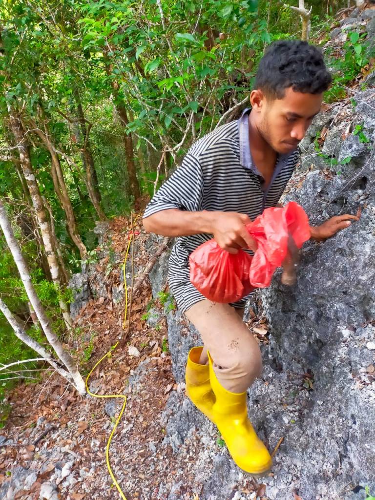
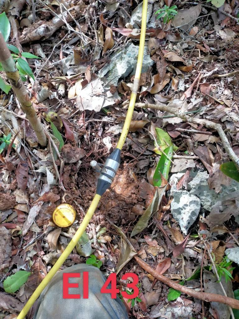
Field Setup Using SuperSting R8
- Lay out the electrode line over the survey area.
- Insert electrodes into the ground at regular intervals.
- Connect electrodes to the SuperSting R8 using a switch box.
- Configure survey parameters:
- Select array type (e.g., Dipole-Dipole for cavities).
- Set current injection and stacking to reduce noise.
- Start data acquisition and monitor real-time data for anomalies.
3. Data Processing & Interpretation
Step 1: Data Pre-Processing
- Remove noisy readings from poor electrode contact.
- Apply topographic corrections if needed.
Step 2: Resistivity Inversion
Use software like EarthImager 2D/3D or Res2DInv to generate a resistivity model.
- Air-filled cavities appear as very high resistivity anomalies (>1000 Ωm).
- Water-filled cavities show moderate resistivity (10–500 Ωm).
- Clay-filled voids appear as low-resistivity zones (1–50 Ωm).
- Weathered limestone has a more gradual resistivity variation.
Step 3: Identifying Cavity Anomalies
- Look for high-resistivity zones that contrast sharply with surrounding limestone.
- Verify anomaly shape: irregular, rounded, or vertically elongated structures suggest karst cavities.
- Cross-check with borehole or GPR data (if available) for confirmation.
4. Case Study Example
Survey Setup
- Electrode spacing: 3m
- Array type: Dipole-Dipole
- Survey length: 60m
- Depth of investigation: ~15m
Results
- A high-resistivity anomaly (~2000 Ωm) at 6m depth, approximately 5m wide → Indicates a possible air-filled cavity.
- A moderate-resistivity zone (~100 Ωm) at 12m depth → Possible water-filled void.
- Low-resistivity region (~30 Ωm) surrounding the void → Suggests clay or weathered limestone infill.
5. Conclusion & Recommendations
✔ Use Dipole-Dipole for high-resolution cavity mapping.
✔ Combine resistivity with borehole/GPR data for verification.
✔ Perform repeat surveys if seasonal groundwater changes are expected.

Tinggalkan komentar