The resistivity method is an effective geophysical technique for detecting subsurface cavities. The SuperSting R8 is an advanced multi-channel resistivity imaging system used to map electrical resistivity variations in the subsurface, which helps identify voids, sinkholes, or other anomalies.
1. Principles of Cavity Detection Using Resistivity
Cavities, voids, and air-filled spaces exhibit high resistivity because air (or dry voids) is a poor conductor of electricity. Conversely, water-filled cavities can have either moderate or low resistivity, depending on the water’s salinity.
Resistivity Trends for Different Subsurface Materials
| Material | Resistivity Range (Ωm) |
|---|---|
| Air-filled cavity | Very high (>1000 Ωm) |
| Water-filled cavity | Moderate (10–100 Ωm) |
| Clayey soil | Low (1–50 Ωm) |
| Sandy soil | Moderate (50–500 Ωm) |
| Limestone (intact) | Moderate (100–1000 Ωm) |
2. Data Acquisition with SuperSting R8
Survey Design
- Choose electrode spacing based on the expected cavity size and depth (e.g., 1–5 meters spacing).
- Use a 2D or 3D resistivity survey for a comprehensive image.
- Common array types:
- Dipole-Dipole (good for lateral resolution and deeper cavities).
- Wenner-Schlumberger (balanced sensitivity for depth and lateral variations).
- Gradient Array (fast for large-area surveys).
Field Procedure
- Set up the electrode line with stainless steel or graphite electrodes.
- Connect electrodes to the SuperSting R8 system using the switch box.
- Select survey parameters (e.g., current injection, stacking, measurement cycles).
- Start data acquisition, allowing SuperSting R8 to record resistivity values at multiple depths.
3. Data Processing & Interpretation
Step 1: Data Filtering
- Remove noisy or outlier readings caused by poor electrode contact or interference.
- Apply topographic corrections if necessary.
Step 2: Resistivity Inversion
- Use software like EarthImager 2D/3D or Res2DInv to convert raw apparent resistivity into a depth model.
- Generate a pseudosection and a true resistivity model.
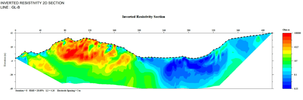
Step 3: Identifying Cavities
- Look for high-resistivity anomalies (possible air-filled cavities).
- Water-filled cavities appear as moderate resistivity zones.
- Ensure anomalies are not due to boulders, compacted zones, or artifacts.
Example Interpretation
- High-resistivity (≥1000 Ωm) = Possible air-filled void.
- Moderate resistivity (50–500 Ωm) = Water-filled void.
- Surrounding low to moderate resistivity = Normal soil or weathered rock.
4. Case Study Example
Survey Setup:
- Electrode spacing: 2m
- Array used: Dipole-Dipole
- Depth of investigation: 10–15m
Results:
- A high-resistivity anomaly (~1500 Ωm) at 5m depth, 4m wide, suggesting an air-filled cavity.
- A moderate-resistivity anomaly (~100 Ωm) at 10m depth, possibly indicating a water-filled void.
5. Advantages of Using SuperSting R8 for Cavity Detection
✔ Multi-channel system → Faster data acquisition.
✔ High-resolution imaging → Clearer subsurface details.
✔ Compatible with 2D and 3D surveys → Better spatial coverage.
✔ Supports multiple array types → More flexibility for different site conditions.

Tinggalkan komentar